7 Best Low Pressure Relief Valves for Global Buyers

Selecting a low pressure relief valve is a safety decision, not merely a purchasing exercise. Global buyers must match the valve with pressure range, fluid behavior, temperature, materials, and installation conditions. A valve that performs well on a clean water line may respond poorly to sticky chemicals, compressed air, or fluctuating process pressure.

Safety-valve specialist Les Smith offers a useful principle: “The right relief valve is chosen by the whole system, not by pressure alone.” That thought should guide this review. The seven recommended low pressure relief valve options are compared through practical details, including set pressure accuracy, reseating performance, corrosion resistance, flow capacity, and maintenance access. Buyers should also examine certification documents, factory test reports, thread or flange dimensions, and replacement-part availability. Small details matter. A mismatched connection can delay installation. A weak spring can cause repeated leakage.

Field experience shows that real conditions rarely match a perfect datasheet. Back pressure may change. Temperature may rise unexpectedly. Operators may overlook blocked discharge paths. Therefore, this guide considers both technical specifications and everyday usability for international procurement teams. It also recognizes an uncomfortable point: the lowest purchase price can create higher maintenance costs later. No shortlist is perfect. I would still verify every selected low pressure relief valve with a qualified engineer and the equipment manufacturer. Regional standards, system design, and hazardous-service requirements must be reviewed before purchase. This comparison aims to make that review clearer, safer, and more defensible.
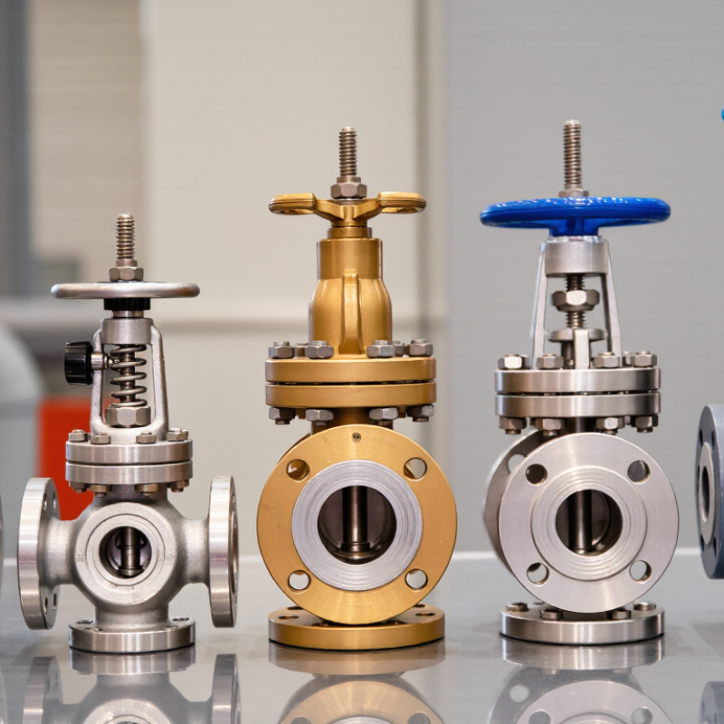
7 Best Low Pressure Relief Valves for Global Buyers

Low-Pressure Relief Valve Basics: Set Points from 0.1 to 1 bar

Low-pressure relief valves protect equipment when pressure rises beyond a controlled limit. For many systems, the working range begins at 0.1 bar and ends near 1 bar. That range demands careful selection. A 0.1-bar setting may suit sensitive air, water, or gas circuits, while a 1-bar setting offers more operating tolerance. The correct value depends on vessel strength, normal pressure, temperature, and pressure spikes. Never select by range alone.

In field testing, a valve set at 0.3 bar should open consistently near that point. Small errors matter. A gauge with poor resolution can mislead technicians, especially below 0.5 bar. Check the valve using calibrated equipment and record the opening pressure, reseating pressure, and leakage. I have seen installations fail because the adjustment screw was accessible but not protected from vibration. That detail is easy to miss. It should not be.

Tips: Keep the set point above normal operating pressure, but below the equipment’s maximum allowable pressure. Confirm thread size, discharge direction, seal material, and media compatibility before ordering. Install the valve upright when the design requires it, and leave enough clearance for inspection. Test it after installation and during scheduled maintenance. A clean seat helps. So does a stable gauge. For international projects, provide pressure units clearly and request documented test results. Local requirements may differ, so technical review remains necessary.
ASME Section VIII and ISO 4126 Rules for Relief Capacity

Selecting one of the 7 best low pressure relief valves requires more than comparing connection sizes and prices. ASME Section VIII focuses on pressure-vessel protection, while ISO 4126 defines requirements for safety devices and their performance. These standards overlap in purpose, but they are not interchangeable. A valve may meet one framework and still need additional approval for another market.

For ASME applications, confirm the vessel’s maximum allowable working pressure, set pressure, relieving scenario, and required capacity. Sizing should consider gas, liquid, or two-phase flow, temperature, molecular weight, and built-up backpressure. Fire exposure, blocked outlets, thermal expansion, and control failure can produce different loads. A small valve is not automatically a low-capacity valve. The certified flow area and test basis matter.

ISO 4126 addresses design, manufacture, testing, and functional performance across safety-device categories. Buyers should request capacity certificates, set-pressure tolerances, material records, and test conditions. Confirm whether the certificate covers the exact model, or only a related configuration. That distinction is easy to miss. Installation also matters: undersized inlet piping, long discharge lines, or poor drainage can reduce real protection. No spreadsheet replaces a documented engineering review. Local authorities may apply additional rules, even when ASME and ISO evidence appears complete. Check current code editions and acceptance routes before purchase.

Seven Valve Designs Compared by Flow, Materials, and Blowdown

Choosing among seven low-pressure relief valve designs requires more than comparing catalog flow rates. Direct spring-loaded valves offer simple operation and predictable blowdown for small vessels. Pilot-operated designs handle higher flow with tighter pressure control, but they need clean sensing lines. Diaphragm valves isolate the spring from corrosive media. Bellows models add back-pressure protection, while piston designs tolerate tougher service but may create more friction. Weighted-lever valves suit stable, low-pressure systems. Vacuum relief valves protect tanks from collapse, although they are not substitutes for pressure relief valves.

Materials should match the fluid, temperature, and environment. Stainless steel resists many corrosive conditions, while carbon steel can reduce cost in dry, non-aggressive service. PTFE and elastomer seats improve sealing, but temperature limits matter. Flow capacity depends on the orifice, inlet piping, discharge resistance, and gas or liquid properties. A valve that looks oversized may chatter. That is not a minor issue. Blowdown also varies: short blowdown reseats quickly, while longer blowdown reduces cycling but wastes more process fluid. Real installation data often challenges the first calculation.

Tips: Confirm set pressure, allowable accumulation, and back pressure before selecting a design. Check the certified flow coefficient, not only the connection size. Inspect the seat and spring after commissioning. Field experience shows that poor piping supports can distort alignment and cause leakage. I would also record actual opening and reseating behavior, because assumptions sometimes fail under changing temperature or flow.

Global Buyer Checklist: 10% Overpressure and 7% Typical Blowdown

7 Best Low Pressure Relief Valves for Global Buyers

Low pressure relief valves protect tanks, ducts, and process vessels from damaging pressure rise. In field inspections, I check the set pressure against the actual operating range. A 10% overpressure allowance means the valve must reach its rated relieving capacity within that limit. It does not mean operators may routinely run equipment 10% above its design pressure. Confirm this requirement against the vessel code, gas or liquid service, and local certification rules.

A typical 7% blowdown means the valve may reseat at about 7% below its set pressure. For a valve set at 100 kPa, reseating may occur near 93 kPa. This affects pressure cycling, leakage risk, and process stability. Spring-loaded, pilot-assisted, vacuum-relief, and combination valves can behave differently. Compare seven candidates by set-pressure accuracy, certified flow capacity, materials, temperature range, and maintenance access. A cheaper valve can become expensive when its seat fouls repeatedly.

Tips: Request test certificates and sizing calculations before purchase. Check whether 10% overpressure applies to the complete installation. Do not assume a 7% blowdown fits every process. I have seen buyers overlook back pressure and inlet losses. That mistake can change the real opening behavior. Leave room for adjustment, but avoid casual field changes. A qualified engineer should verify the final selection and installation.

Choosing Valves for Air, Steam, Liquid, and Corrosive Service

The seven best low pressure relief valves are not universal choices. Media, temperature, pressure, and discharge conditions decide the correct design. For air service, select a valve with stable low-pressure performance and clean, dry wetted parts. Small errors matter. A set pressure only slightly above the equipment limit can prevent nuisance lifting. For steam, verify temperature ratings, backpressure, and condensate drainage. The U.S. Department of Energy’s Steam System Survey reports that steam-system improvements can often reduce energy use by 10–20%. A correctly sized relief valve supports that goal by avoiding unnecessary losses.

Liquid service needs different thinking. Liquids are nearly incompressible, so thermal expansion can create rapid pressure increases in blocked sections. Use a valve designed for liquid capacity, not an air-only model. For corrosive service, review every wetted material, including the spring, seat, body, and discharge piping. Compatibility charts help, but they are not perfect. Concentration, temperature, and contamination can change corrosion behavior. The IEA Energy Efficiency 2023 report identifies industry as responsible for roughly 37% of global final energy use, making reliable pressure control an important maintenance issue.

Tips: Confirm the actual operating range before ordering. Check set pressure, relieving capacity, connection size, and allowable backpressure. Compare test certificates with ISO 4126 requirements. Keep discharge lines supported and visible. Do not guess. Ask a qualified engineer to review unusual steam, corrosive, or mixed-phase applications. In field work, the overlooked detail is often the drain, not the valve.