How to Choose Aluminum Profiles for Solar Panel Frames
Solar installations are scaling rapidly, and frame choices affect more than appearance. IRENA’s Renewable Capacity Statistics 2024 reports that global solar capacity reached 1,419 GW in 2023, after adding 345.5 GW that year. That scale matters. As projects grow, small differences in extrusion quality, fit, and corrosion resistance can influence assembly speed and long-term maintenance.
Choosing an Aluminum Profile For Solar Panel Frame means balancing structural performance with cost, weight, and manufacturing needs. The right section depends on panel dimensions, mounting design, wind and snow loads, and the connection details used on site. Alloy and temper matter, but so do wall thickness, tolerances, surface treatment, and drainage around joints. A thick profile is not automatically a better one. It may add weight without solving the actual load problem.
This guide explains how to assess those choices using practical criteria and information from established industry sources, including IRENA and the International Energy Agency’s PVPS programme. It also highlights questions to raise with suppliers, such as whether test data matches the proposed alloy, finish, and profile geometry. A datasheet can look convincing. Yet real projects reveal details that a neat specification may miss, and that deserves a closer look.
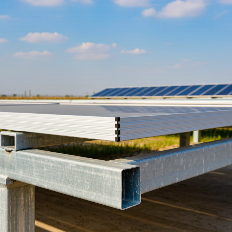
Understand the Structural and Environmental Demands on Solar Panel Frames
Solar frames carry more than module weight. They resist wind uplift, snow accumulation, handling loads, and repeated temperature changes. A roof edge or open field can face much higher wind exposure than a sheltered site. Snow may also drift unevenly, loading one rail or corner more heavily. This detail is easy to underestimate. Aluminum profiles should be sized around the full load path, including clamps, fasteners, joints, and support spacing—not just the rail’s visible thickness.
IEC 61215-2:2021 includes module mechanical-load qualification tests at 2,400 Pa, with a 5,400 Pa front-load option where specified. These are module test pressures, not automatic design ratings for a frame or project. Use site-specific wind and snow loads under applicable structural standards, such as ASCE/SEI 7-22, and confirm profile strength, deflection, and connection capacity with an engineer. Coastal salt, trapped moisture, and contact with dissimilar metals also raise corrosion risks. Allow for thermal movement; tightly fixed rails can stress joints as temperatures swing.
Tips: Ask for load calculations at the actual support spacing, plus alloy, temper, and finish specifications. Check drainage paths and fastener compatibility. A thicker profile can still disappoint if its connection details are weak.
Define Load, Span, and Dimensional Requirements for the Profile
For a solar panel frame, define the design load before choosing an aluminum profile. Wind uplift, snow, panel weight, and maintenance loads all affect the required section. ASCE/SEI 7-22 provides methods for determining site-specific wind and snow loads; the correct values depend on location, roof height, exposure, and installation angle. Do not treat a catalog span as a safe span for every project. A longer unsupported span can sharply increase deflection: under uniform loading, a simple beam’s deflection varies approximately with the fourth power of its span.
Then set the clear span, support locations, and dimensional limits, including panel-edge engagement and clamp space. The Aluminum Association’s Aluminum Design Manual lists a minimum yield strength of about 25 ksi for qualifying 6063-T6 products in thinner sections. Actual allowable design strength depends on product thickness, temper, and design factors, so verify supplier certificates and applicable design tables. A deeper profile may improve stiffness, but it can also interfere with drainage or panel fit. Small details matter.
Tips: Write down load, span, allowable deflection, and maximum profile width before requesting quotations. Ask an engineer to check the weakest orientation and connection. A profile can look sturdy and still twist under uplift; that detail is easy to underestimate.
Compare Aluminum Alloys and Tempers for Strength and Durability
For solar panel frames, alloy and temper matter as much as the profile shape. 6063 is widely used for extruded frames because it forms complex channels and takes a smooth finish. In T5 or T6 temper, it can provide useful strength for many rooftop assemblies. 6061-T6 generally offers higher strength, but intricate shapes may be harder to extrude. Stronger is not automatically better.
Temper describes how the alloy was processed, so compare supplier data for the exact profile, not just the alloy number. T5 is artificially aged after cooling from extrusion; T6 receives solution heat treatment and artificial aging. The resulting properties can vary by section thickness and production process. Details matter. Check the corners.
Corrosion resistance also deserves attention, especially where cut ends or fasteners meet. A sound coating can help, but it cannot compensate for poor drainage or trapped moisture inside a channel. Match profile strength to panel span, wind loading, and support spacing, using engineering calculations for the project. A frame that feels rigid on a workbench may flex across a long roof span. The choice is not always tidy: a readily available 6063 profile may suit the design better than a stronger alloy that requires a heavier or less practical section. Verify temper, dimensions, and test documentation before ordering.
Check Surface Finish, Fabrication, and Compatibility Requirements
How to Choose Aluminum Profiles for Solar Panel Frames
A smooth profile is not automatically a durable one. Inspect the finish for thin spots, scratches, and uneven color, especially near corners and screw slots. These areas often reveal handling or coating problems. Ask whether the finish is intended for the project’s exposure conditions, and request a sample that has undergone the same finishing process as the production run. A small coupon can help, but it cannot show every batch variation.
Check the fabrication details before approving a profile. Cut ends should be square, with no sharp burrs that could damage seals or wiring. Confirm hole positions, slot dimensions, and tolerances against the assembly drawing. Even a few millimeters of mismatch can complicate installation. Test a short section with the planned fasteners and clamps; do not assume a familiar profile will fit a new layout. I have seen tidy drawings hide awkward tool access.
Compatibility deserves equal attention. The frame must suit the panel thickness, mounting hardware, and any seals or isolation pads in the design. Consider drainage paths so water does not sit inside channels, and allow for thermal movement across long runs. Check material and finish compatibility where dissimilar metals meet, particularly around fasteners. A neat sample can still mislead. Record the approved dimensions and finish, then compare delivered profiles with that reference before assembly.
How to Choose Aluminum Profiles for Solar Panel Frames
Check surface finish, fabrication, and compatibility requirements. Thermal expansion is one compatibility factor to consider when selecting a frame profile.
Compatibility: Approximate room-temperature linear thermal expansion coefficients are shown in micrometres per metre per degree Celsius. Aluminum expands more than typical soda-lime glass, so consider temperature-related movement in the frame and mounting design. Actual values vary with alloy and material composition.
Selection checks: Confirm the finish type and required coating specification; verify profile tolerances, machining, and drainage features; and check that the frame is compatible with the module materials and mounting system.
 North American Safety Valve Industries, Inc.