How to Choose the Right Safety Valve for Your System?
Choosing the right safety valve begins with understanding the system, not browsing a catalogue. Every process has a different pressure profile, fluid behavior, temperature range, and failure risk. A valve protecting a steam line may perform poorly on a corrosive chemical vessel. The details matter.
Process-safety expert Trevor Kletz often warned, “If you think safety is expensive, try an accident.” His words remain practical today. A correctly selected safety valve can protect workers, equipment, production schedules, and the surrounding environment. It must open at the correct set pressure, discharge enough flow, and close without dangerous chatter. Small errors can become serious.
Begin with the maximum allowable working pressure. Then examine operating pressure, temperature, fluid phase, backpressure, and required relieving capacity. Check whether the medium contains solids, sticky materials, or corrosive compounds. These conditions influence the trim, body material, connection type, and valve design. Installation details matter too. A long, narrow inlet pipe can create pressure loss before the valve even responds.
Do not rely on set pressure alone. Ask how the valve will be tested, maintained, isolated, and inspected. A safety valve that cannot be reached safely is not a complete solution. Vendor calculations and recognized engineering standards should support the final choice. Still, no selection is perfect without field knowledge. Flow data may be incomplete. Operating conditions may change. Good engineers admit those gaps, verify assumptions, and review the choice with qualified process, mechanical, and safety professionals. The safest decision is usually the one that survives real operating conditions, not merely a spreadsheet.
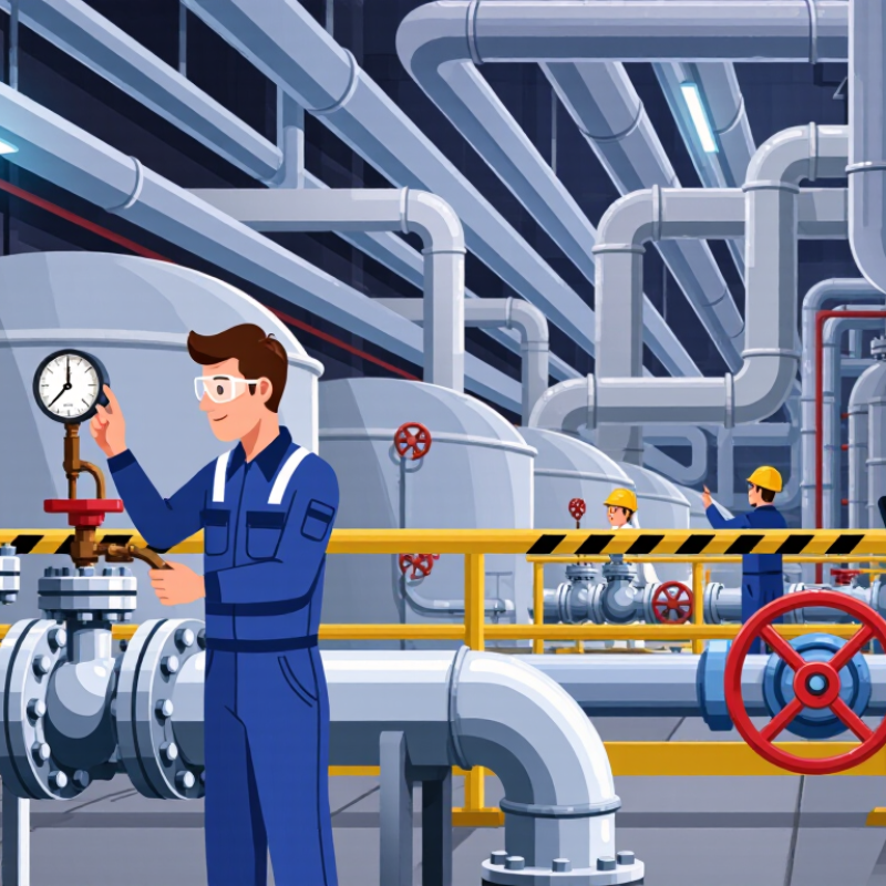
Define the System’s Pressure, Temperature, and Fluid Conditions
How to Choose the Right Safety Valve for Your System?
Define the system’s pressure, temperature, and fluid conditions before selecting a safety valve. Record normal operating pressure, design pressure, set pressure, and possible pressure surges. For many ASME Section VIII applications, allowable accumulation is commonly 10%. Fire exposure may permit 21%, but the governing code must confirm this value. API 520 Part I and API 521 provide recognized methods for sizing and discharge analysis.
Temperature changes everything. A cold-start condition can make a liquid more viscous. A hot process can weaken valve materials or create flashing. Identify whether the fluid is liquid, vapor, gas, or a two-phase mixture. Check density, viscosity, corrosiveness, toxicity, and solids content. ISO 4126-1 emphasizes performance requirements for safety valves, yet field conditions are often less tidy than design sheets suggest. A clean calculation can still miss a blocked outlet, rapid boiling, or backpressure from a long discharge pipe.
Tips: Create a pressure-temperature-fluid matrix. Include normal, upset, startup, shutdown, and fire scenarios. Verify certified capacity under the actual fluid conditions. Review built-up and superimposed backpressure separately. Keep inspection records practical and current. Do not assume yesterday’s valve suits today’s process. Talk with the relief-system engineer. Safety depends on details.
How to Choose the Right Safety Valve for Your System?
Define the system’s pressure, temperature, and fluid conditions before selecting the valve body, trim, spring range, and discharge configuration.
The chart shows representative industrial design conditions. Pressure is shown in bar absolute and temperature in °C. Saturated steam at 16 bar absolute is approximately 201 °C. Actual valve selection must also consider phase, corrosiveness, back pressure, required relieving capacity, and applicable pressure-equipment standards.
Identify the Safety Valve Type and Operating Mechanism
How to Choose the Right Safety Valve for Your System?
Identify the Safety Valve Type and Operating Mechanism
Choosing a safety valve starts with understanding the hazard and the process conditions. A spring-loaded safety valve is common in steam, gas, and liquid systems. It opens when system pressure overcomes the spring force. A pilot-operated valve uses process pressure to control the opening action. It can provide stable performance in high-pressure systems, but it needs clean pilot lines.
Check whether the system requires a safety valve, relief valve, or combination design. Safety valves usually open rapidly and protect against sudden overpressure. Relief valves often open gradually as pressure rises. Material compatibility matters too. A corrosive fluid can damage internal parts, even when the pressure rating appears suitable. Review set pressure, temperature, discharge capacity, connection size, and back pressure. Small details can change the result. In practice, selection mistakes often come from using normal operating pressure instead of the actual design pressure.
Tips: Confirm the valve’s operating mechanism with the system engineer. Test lifting performance under controlled conditions. Inspect the spring, seat, and discharge path during maintenance. Do not assume a larger valve provides better protection. An oversized valve may chatter, leak, or close unpredictably. Pilot-operated designs require extra attention to sensing lines. Keep these lines short, clean, and protected from freezing. Documentation should record the set pressure and test date. One overlooked detail can weaken an otherwise sound protection system.
Set the Correct Pressure Rating and Blowdown Range
How to Choose the Right Safety Valve for Your System?
Set the pressure rating from verified system data, not habit. Confirm the equipment’s maximum allowable working pressure, normal operating pressure, and credible upset conditions. The valve set pressure must protect the weakest pressure boundary. It should also allow stable operation during normal pressure fluctuations. Leave practical margin above the operating pressure, but never exceed the equipment rating. I have seen valves selected from outdated drawings. That mistake can create nuisance lifting or delayed protection.
Blowdown is equally important. It is the pressure difference between opening and reseating. A narrow blowdown range may reduce product loss, but it can cause rapid cycling when pressure remains unstable. A wider range may improve reseating, yet it can temporarily lower system pressure. Match the range to the process response, fluid behavior, and required capacity. Consider built-up backpressure, superimposed backpressure, temperature, and installation losses. These details often change actual valve performance.
Check the pressure rating at operating temperature. Metal strength can decrease as temperature rises. Verify cold differential test pressure when the valve is adjusted away from service conditions. Record the final set pressure and test method. Field conditions are rarely perfect. That deserves attention. A practical review with operations and maintenance staff can expose assumptions hidden in the design file. Recheck the choice after commissioning, especially if the valve lifts unexpectedly or reseats unevenly.
How to Choose the Right Safety Valve for Your System? - Set the Correct Pressure Rating and Blowdown Range
| Service or Application |
Typical Set-Pressure Range |
Typical Blowdown Target |
Recommended Pressure-Rating Check |
Key Selection Consideration |
| Low-pressure steam |
3–10 barg
43–145 psig |
Approximately 2–4% of set pressure |
Valve set pressure should not exceed the protected equipment MAWP. Confirm the pressure rating at the actual steam temperature. |
Select a steam-rated valve with stable reseating after overpressure relief and sufficient certified capacity. |
| High-pressure steam |
10–40 barg
145–580 psig |
Approximately 3–7% of set pressure |
Check the valve body, spring, trim, flange, and gasket ratings at the design temperature and relieving pressure. |
Use certified steam capacity data and verify that discharge piping can safely handle the reaction forces and temperature. |
| Compressed air or non-hazardous gas |
5–50 barg
73–725 psig |
Approximately 5–10% of set pressure |
The pressure rating must exceed the maximum allowable relieving pressure at the operating temperature, not only the normal operating pressure. |
Confirm gas service compatibility, required flow capacity, backpressure limits, and discharge vent routing. |
| Flammable or toxic gas |
5–100 barg
73–1,450 psig |
Typically 3–7%; verify the governing code |
Check body and trim materials, design temperature, allowable built-up backpressure, and the complete connected discharge system. |
A closed discharge system, compatible materials, leak-tight performance, and controlled backpressure are normally required. |
| Liquid service |
2–20 barg
29–290 psig |
Approximately 2–5% of set pressure |
Verify the pressure rating at the liquid temperature and ensure the valve is sized using liquid-relief capacity methods. |
Check for liquid flashing, viscosity, two-phase flow, inlet pressure loss, and adequate drainage from the outlet. |
| Thermal relief for blocked-in liquid |
5–25 barg
73–363 psig |
Approximately 2–5% of set pressure |
Set pressure must protect the lowest-rated component exposed to thermal expansion. |
Small capacity may be sufficient, but the valve must account for the maximum credible heat input and liquid expansion rate. |
| Boiler or fired-heater protection |
Based on boiler MAWP and applicable code |
Commonly 2–4% for steam applications; verify the applicable code limit |
Use the required code-certified pressure rating, capacity, and accumulation limits for the boiler design. |
Set pressure, accumulation, relieving capacity, and valve quantity must be evaluated together. |
Pressure-rating and blowdown rules:
The valve set pressure should normally be at or below the protected equipment's maximum allowable working pressure (MAWP). Verify the allowable accumulation, relieving pressure, operating temperature, built-up and superimposed backpressure, and required relieving capacity under the applicable local code and design standard. Blowdown values shown above are typical engineering ranges only; the certified valve adjustment range and governing code requirements take precedence.
| Selection Parameter |
Practical Check |
Why It Matters |
| Set pressure |
Set pressure ≤ equipment MAWP unless the governing code explicitly permits another arrangement. |
Prevents the protected equipment from exceeding its allowable design pressure. |
| Operating pressure |
Maintain normal operating pressure sufficiently below the set pressure to avoid simmering or frequent lifting. |
Improves seat tightness, stability, and service life. |
| Blowdown |
Choose the lowest stable blowdown that meets the applicable code and process requirements. |
Affects reseating pressure, product loss, cycling risk, and system stability. |
| Pressure class or flange rating |
Select the pressure class only after checking pressure–temperature rating tables for the actual material and temperature. |
Nominal flange classes are not interchangeable with a single fixed allowable pressure at every temperature. |
| Relieving capacity |
Size the valve for the largest credible overpressure case, including fire, blocked outlet, thermal expansion, or control-valve failure where applicable. |
Ensures the valve can reduce pressure before the protected equipment exceeds its permitted limit. |
| Backpressure |
Calculate superimposed and built-up backpressure and compare them with the valve's certified limits. |
Excessive backpressure can alter set pressure, capacity, blowdown, and valve stability. |
 North American Safety Valve Industries, Inc.