 North American Safety Valve Industries, Inc.North American Safety Valve Industries, Inc.North American Safety Valve Industries, Inc.
A storage tank may appear calm while pressure changes inside it. Temperature shifts, filling operations, and liquid removal can all disturb its internal balance. A pressure vacuum relief valve helps control these changes by releasing excess pressure or admitting air when a vacuum develops. Without suitable protection, tank walls, seals, and connected equipment may suffer damage. The consequences can begin with a distorted roof or a leaking gasket.
This article explains how a pressure vacuum relief valve works, where it is installed, and why correct sizing matters. It also considers set pressure, flow capacity, maintenance, and material selection. These details are not merely technical paperwork. A technician may inspect a valve outdoors, noticing corrosion around the spring housing or residue near the seat. That small observation can reveal a larger reliability concern.
Experienced engineers normally review tank design data, operating conditions, and the manufacturer’s certified information before selecting a valve. Applicable industry standards should also be checked for the specific service and location. Requirements can differ between atmospheric tanks, process vessels, and specialized storage systems. Assumptions are risky here. A valve that fits the nozzle may still provide inadequate protection.
Reliable performance depends on more than the valve itself. Installation orientation, vent piping, weather protection, and scheduled testing all influence operation. Some maintenance plans look complete but overlook blocked vents or sticky seats. That is worth reconsidering. Understanding these practical points makes pressure and vacuum protection easier to evaluate, document, and manage with confidence.
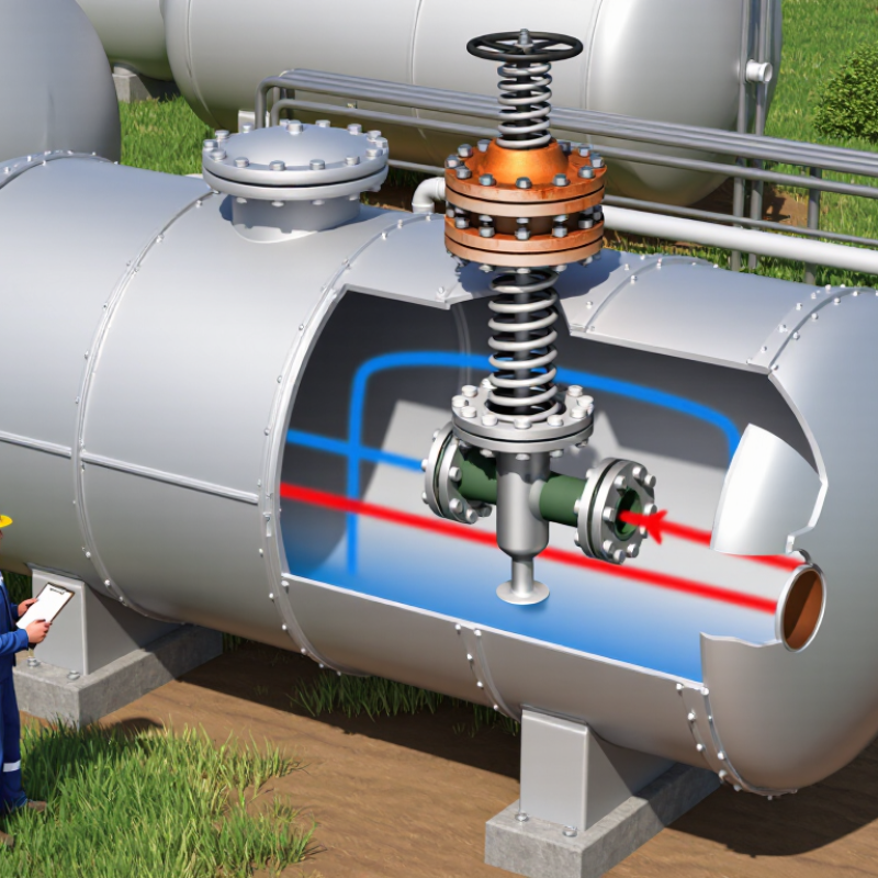
A pressure vacuum relief valve protects storage tanks from excessive pressure and vacuum. It opens when vapor pressure rises above a safe setting. It also admits air when internal pressure falls below the tank’s design limit. This simple action helps prevent shell deformation, roof damage, and uncontrolled vapor release.
The valve’s purpose is operational, not decorative. API Standard 2000 provides widely used guidance for venting atmospheric and low-pressure storage tanks. Its sizing approach considers filling, emptying, thermal breathing, and emergency conditions. The U.S. EPA’s 2024 Inventory estimates that petroleum and natural gas systems produced about 198.9 million metric tons of carbon dioxide equivalent in 2022. That figure shows why reliable vapor control matters. A poorly adjusted valve can waste product, increase emissions, or fail during a rapid temperature change. In practice, no setting is perfect. Tank inspection data, fluid behavior, and local weather should influence the final selection.
Tips: Confirm the set pressure against the tank’s design pressure. Check flame screens, seats, and vent paths during scheduled maintenance. Keep records of testing and cleaning. Do not assume a quiet valve is a healthy valve. A stuck valve may remain silent until the tank is already stressed. Operators should also verify capacity under both pressure and vacuum conditions, because many failures begin with an overlooked vacuum scenario.
| Data Dimension | Definition or Technical Information | Operational Significance |
|---|---|---|
| Device Name | Pressure Vacuum Relief Valve, commonly abbreviated as PVRV. | A combined atmospheric tank protection device that controls both excessive internal pressure and excessive vacuum. |
| Primary Purpose | To release or admit gas when the pressure inside a storage tank moves beyond the valve’s configured operating limits. | Helps prevent tank damage caused by overpressure or implosion while reducing unnecessary product vapor loss. |
| Pressure-Relief Function | The pressure pallet or spring-loaded pressure element opens when tank pressure exceeds the pressure set point. | Relieves excess vapor generated by filling, temperature increase, evaporation, or external fire exposure, depending on the system design. |
| Vacuum-Relief Function | The vacuum pallet or spring-loaded vacuum element opens when tank pressure falls below the vacuum set point. | Allows atmospheric air or an approved inert gas to enter the tank during emptying, cooling, condensation, or vapor withdrawal. |
| Typical Installation | Usually mounted on the roof or vapor-space nozzle of low-pressure or atmospheric storage tanks. | Provides direct protection to the tank vapor space and is normally installed where the valve can be inspected and maintained safely. |
| Typical Applications | Used on tanks storing petroleum liquids, solvents, chemicals, water-treatment products, and other liquids that generate or contain vapors. | Suitable when the tank requires controlled vapor movement and protection against pressure fluctuations during normal operation. |
| Pressure Set Point | The pressure at which the pressure-relief element is designed to begin opening. The value is selected according to the tank design pressure and operating requirements. | The set point must remain below the tank’s allowable working pressure to provide effective protection. |
| Vacuum Set Point | The negative pressure at which the vacuum-relief element is designed to begin opening. It is commonly specified in pascals, millimetres of water column, or inches of water column. | The set point must be compatible with the tank’s allowable vacuum rating to reduce the risk of buckling or collapse. |
| Normal Operating Range | The pressure range in which both the pressure and vacuum elements remain closed while maintaining tank integrity. | Correct sizing and set-point selection help prevent unnecessary valve lifting, vapor emissions, and product contamination. |
| Main Operating Media | Tank vapor, air, inert gas, or process vapor, depending on the stored liquid and the tank’s blanketing arrangement. | Material compatibility and emission-control requirements depend on the composition, temperature, and hazardous properties of the media. |
| Common Valve Designs | Weighted-pallet, spring-loaded, pilot-assisted, and conservation-vent designs are used for different pressure ranges and service conditions. | The design affects response characteristics, maintenance requirements, allowable pressure range, and resistance to sticking. |
| Construction Materials | Common materials include carbon steel, stainless steel, aluminium, and corrosion-resistant alloys, selected according to the stored product and environment. | Material selection helps control corrosion, leakage, contamination, and premature component failure. |
| Connection Types | Typical connections include flanged, threaded, and sometimes wafer-style arrangements, depending on valve size and installation design. | The connection must match the tank nozzle, piping layout, gasket material, and applicable engineering requirements. |
| Sizing Factors | Sizing commonly considers liquid filling and withdrawal rates, vapor generation, thermal breathing, fire exposure, gas composition, and allowable tank pressure or vacuum. | An undersized valve may not protect the tank adequately, while an oversized or poorly selected valve may operate inefficiently. |
| Emission-Control Role | The valve remains closed during normal conditions and opens only when pressure or vacuum reaches the applicable operating threshold. | This can reduce routine vapor emissions compared with an unrestricted open vent, although additional vapor-control equipment may still be required. |
| Safety Limitations | A PVRV is not automatically a substitute for an emergency vent, rupture disk, flame arrester, or independent fire-protection system. | Additional protective devices may be necessary when required by tank design, process hazards, fire scenarios, or applicable regulations. |
| Inspection and Maintenance | Maintenance may include checking pallets, seats, guides, springs, weather hoods, screens, gaskets, corrosion, and freedom of movement. | Regular inspection helps detect fouling, sticking, corrosion, blocked openings, and changes in set-point performance. |
| Relevant Industry References | Common engineering references include API 2000 and ISO 28300 for venting atmospheric and low-pressure storage tanks. | The applicable edition, local regulations, tank code, and site requirements should be reviewed during design and selection. |
| Core Design Objective | To maintain tank pressure within safe operating limits while allowing controlled vapor discharge and controlled air or gas admission. | Proper application supports tank integrity, operational reliability, environmental control, and process safety. |