2026 Best Hydraulic Relief Valve Types for Buyers

A hydraulic relief valve may look like a compact steel fitting, but its setting can shape the safety, efficiency, and service life of an entire hydraulic system. For buyers, choosing well means looking beyond port size and price. Pressure range, flow capacity, response behavior, fluid compatibility, and adjustment style all matter. A valve that works smoothly on a test bench may behave differently in a hot plant room or a machine with sharp pressure spikes.

Hydraulic control systems author Herbert E. Merritt offers a useful foundation for this decision. The following is a paraphrase of his engineering perspective, not a verbatim quotation: “Reliable hydraulic control depends on matching the valve to the system’s operating conditions.” That principle is easy to overlook. It is also where many purchasing decisions go wrong.

This 2026 guide compares the main hydraulic relief valve types, including direct-acting and pilot-operated designs, and explains where each can be a sensible fit. It also highlights practical checks buyers can make before ordering, from confirming pressure settings to reviewing manufacturer data and maintenance needs. Details matter. Even a small mismatch can lead to noise, excess heat, or unstable pressure. No single valve suits every application, so the best choice begins with the actual circuit, not a catalog headline.
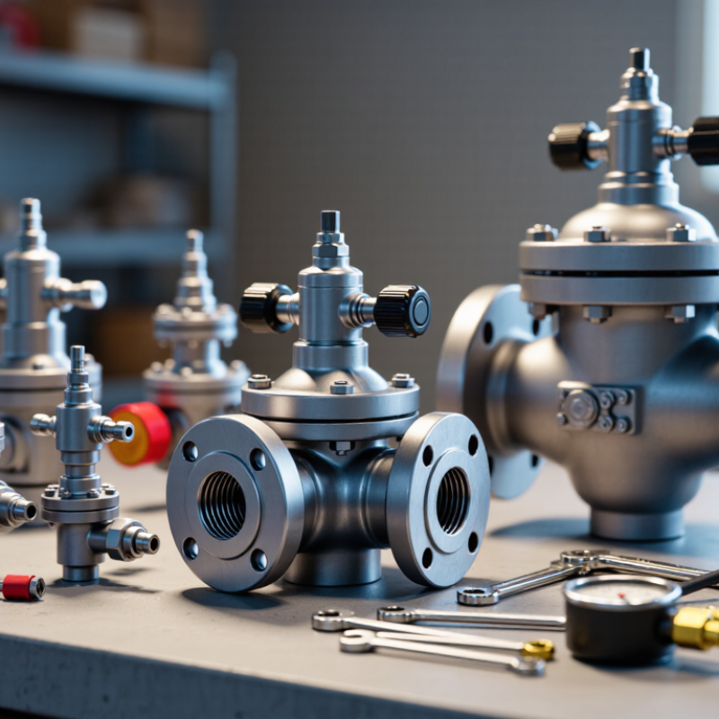
2026 Best Hydraulic Relief Valve Types for Buyers

What Hydraulic Relief Valves Do in a Hydraulic System

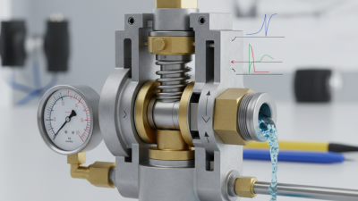
A hydraulic relief valve limits pressure by opening a path from the pressure line to the tank. When a cylinder stalls or a load suddenly rises, pressure pushes the valve toward its set point. The valve then diverts oil, helping protect pumps, hoses, and actuators from excessive pressure. ISO 4413:2010 requires hydraulic systems to be protected against pressures exceeding component limits. The valve is a safety control, not a substitute for correct component ratings or sound maintenance.

The energy cost can be tangible. A valve bypassing 10 litres per minute at 100 bar dissipates about 1.67 kilowatts as heat, using the standard hydraulic power calculation. The U.S. Department of Energy’s Improving Pumping System Performance sourcebook discusses throttling and bypassing as sources of avoidable system losses. In practice, persistent bypass flow can warm the reservoir and shorten fluid life. That matters. A brief pressure spike may be normal; continuous flow over the relief valve deserves investigation. Check the pressure setting with a calibrated gauge, and inspect for contamination or a valve that cannot reseat. I would not treat a single pressure reading as proof of correct operation: temperature, flow, and load conditions can change the result.
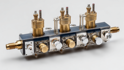
2026 Best Hydraulic Relief Valve Types for Buyers

What hydraulic relief valves do in a hydraulic system: they limit maximum pressure by diverting excess fluid flow back to the tank or another low-pressure circuit.

The chart shows representative pressure-setting ranges commonly encountered in industrial hydraulic systems. Direct-acting valves are simple and fast for compact circuits, pilot-operated valves are preferred for high flow and stable pressure control, proportional valves allow electronically adjustable pressure, and cartridge valves provide high flow capacity in compact manifolds. Actual limits depend on the circuit, fluid, temperature, pressure class, and valve specification.

How Hydraulic Relief Valves Control Pressure

2026 Best Hydraulic Relief Valve Types for Buyers: How Hydraulic Relief Valves Control Pressure

Hydraulic relief valves protect circuits by diverting excess oil when pressure reaches a preset level. A spring-loaded valve reacts directly to pressure. It suits compact systems and moderate flow rates. A pilot-operated valve uses a small control stage, allowing steadier pressure control in larger systems. The choice affects heat, noise, response time, and energy loss.

According to Grand View Research’s Hydraulic Equipment Market Size, Share and Trends Analysis Report, the global hydraulic equipment market was valued at about USD 49.2 billion in 2022. The report also forecasts a 4.8% compound annual growth rate from 2023 to 2030. More equipment means more pressure-control decisions. ISO 4413 stresses safe design, pressure limitation, and proper adjustment of hydraulic systems. In practice, a valve set too low can cause weak actuator movement. Set it too high, and the pump, hoses, or cylinder may face unnecessary stress. A perfect setting rarely exists.

Tips: Set the relief valve above normal working pressure, but below the weakest component’s rated limit. Check pressure with a calibrated gauge near the valve. Inspect the oil temperature after testing. Heat often reveals hidden throttling losses. Do not assume the catalog flow rating matches real conditions. Viscosity, contamination, and return-line restriction can change performance. I would also retest the setting after installation, because a clean test bench does not represent every field circuit.

Major Types of Hydraulic Relief Valves in 2026

Hydraulic relief valves limit pressure by opening a path to tank when system pressure reaches a set point. Direct-acting valves use a spring-loaded poppet or spool. Their response is straightforward and often quick. They suit lower-flow circuits, compact manifolds, and systems where a small pressure rise is acceptable.

Not always.

Pilot-operated valves use a smaller pilot stage to control a larger main valve. They are common in higher-flow circuits and can hold pressure more steadily as flow changes. However, pilot passages need clean oil; contamination can affect response. A technician might check the setting with a calibrated gauge while the machine runs under a controlled load.

Proportional relief valves adjust pressure through an electrical signal, allowing control to change with operating conditions. They can help in equipment that needs different pressure limits during a work cycle.

Cartridge describes a mounting style, not a separate operating principle: a cartridge may be direct-acting or pilot-operated. The categories are not perfectly tidy.

Buyers should compare flow capacity, pressure range, response, oil cleanliness requirements, and port layout. A valve that fits the thread may still behave poorly if its flow rating is too low.

Tank-line back pressure can also shift the actual setting, so verify it in the installed circuit.

How to Compare Relief Valve Specifications

2026 Best Hydraulic Relief Valve Types for Buyers

How to Compare Relief Valve Specifications

Choosing a hydraulic relief valve starts with the working pressure, not the catalog price. Check the normal operating pressure, maximum pressure, and adjustment range. The valve’s set pressure should protect the circuit without opening during ordinary pressure spikes. Leave a practical margin. Too little margin causes nuisance relief; too much may damage pumps, hoses, or actuators.

Compare rated flow with the pump’s peak delivery. A valve that passes 40 liters per minute may perform poorly on a 60-liter system. Review pressure override, response time, and reset behavior. These details show how pressure changes under real load. A simple pressure rating can hide weak performance.

Look closely at connection size, seal material, fluid compatibility, and temperature limits. Confirm whether the valve suits mineral oil, water-based fluid, or another approved medium. Examine leakage data at low pressure. Small internal leakage can heat a compact system over several hours. It matters.

Field inspection also reveals practical issues. Adjustment access may be difficult inside a crowded manifold. Threads can be correct, yet installation space remains insufficient. I once trusted a specification sheet that omitted cold-start behavior. That omission changed the final selection. Buyers should request test curves, calibration records, and applicable manufacturing standards. Independent verification is useful, but it is not perfect. Even good data needs comparison with the machine’s actual duty cycle.

How to Select, Install, and Maintain a Relief Valve

Selecting a hydraulic relief valve starts with the circuit, not the catalog. Record maximum working pressure, normal flow, fluid temperature, and connection size. Choose a direct-acting valve for simple, fast protection. Pilot-operated designs suit higher flow and steadier pressure control. Confirm the pressure range includes the intended setting. A narrow range is better. Check fluid compatibility, seal material, and contamination tolerance before ordering. Field inspections often show incorrect port sizes causing more trouble than complex calculations.

Install the valve close to the pump or protected actuator. Keep the inlet line short, clean, and correctly sized. The outlet must return safely to the reservoir, without back pressure that changes operation. Use a calibrated gauge near the valve during adjustment. Raise pressure gradually, then lock the setting against vibration. Never adjust by guesswork. Ensure discharge cannot spray toward workers or hot surfaces. A missing support bracket can loosen fittings over time.

Maintenance should follow operating hours, not only calendar dates. Inspect for leakage, unusual noise, heat, and pressure drift. Clean strainers and check the return path during scheduled service. Test the set pressure with safe, controlled loading. If readings change repeatedly, investigate contamination, worn seats, or gauge error. Do not replace the valve immediately. The original fault may remain. Document every setting and inspection result. Small records expose patterns that memory misses. A correct valve can still fail when installation discipline is poor. Review the setup after the first heavy-duty cycle.

2026 Best Hydraulic Relief Valve Types for Buyers - How to Select, Install, and Maintain a Relief Valve
Valve Type How It Works Common Uses Key Selection Factors Installation Checks Maintenance Focus
Direct-Acting Relief Valve System pressure acts directly on a spring-loaded poppet or spool. The valve opens when pressure overcomes the spring force and closes as pressure falls. Compact hydraulic circuits, lower-flow systems, and applications where a simple pressure-limiting device is suitable. Check rated pressure, flow capacity, pressure override, response requirements, fluid compatibility, and connection type. Confirm capacity at the intended flow, not only the nominal setting. Install at the specified pressure port and route discharged oil safely to tank. Keep ports clean and use the specified orientation and sealing method. Check for contamination, seat wear, leakage, and pressure-setting drift. A valve that chatters or runs hot may be undersized, contaminated, or operating continuously near its setting.
Pilot-Operated Relief Valve A small pilot stage senses pressure and controls a main stage. This arrangement can provide greater flow capacity and more stable pressure control than a simple direct-acting design in suitable circuits. Higher-flow systems and circuits requiring controlled pressure relief over a wider operating range. Verify flow range, pressure range, pilot-stage requirements, response behavior, leakage characteristics, and whether an external drain connection is required. Connect pressure, tank, and any pilot or drain ports according to the circuit diagram. Keep drain lines unrestricted and at the pressure specified by the valve manufacturer. Inspect pilot passages and screens for contamination. Check drain-line backpressure, internal leakage, and the pressure setting during scheduled testing.
Proportional Pressure-Relief Valve An electrical command adjusts the pressure setting through a proportional solenoid and pilot stage. The actual response depends on the valve, control electronics, and operating conditions. Systems that need electronically adjustable pressure, multiple operating modes, or integration with machine controls. Match the pressure and flow ratings, command signal, electrical supply, connector, control strategy, and fail-safe behavior to the system requirements. Follow the wiring diagram and hydraulic port markings. Protect electrical connections from moisture and vibration, and configure the controller using the specified procedure. Check connectors, wiring, command response, contamination, and pressure accuracy. Diagnose electrical faults separately from hydraulic faults.
Thermal Relief Valve A small relief device opens when thermal expansion raises pressure in a trapped or blocked volume. It is intended to protect that isolated section, not normally to serve as the main system relief valve. Trapped cylinder chambers, blocked lines, or other enclosed oil volumes that can experience pressure rise as temperature changes. Determine the trapped volume, possible temperature range, allowable pressure, discharge destination, and required flow. Confirm that the valve is suitable for thermal protection. Install so the protected volume cannot be isolated from its relief path during normal operation. Route discharge to a safe, suitable return point. Check that the relief path remains open and that the valve has not become blocked, contaminated, or subject to unintended backpressure.
Cartridge-Style Relief Valve A relief-valve mechanism is housed in a cartridge that fits a compatible cavity or manifold. The cartridge format describes its installation form; its operating action may be direct-acting or pilot-operated. Manifold-based circuits, compact equipment, and systems designed around cartridge cavities. Confirm cavity specification, port arrangement, pressure and flow ratings, adjustment range, seals, and compatibility with the manifold design. Clean the cavity and cartridge, use compatible seals, and tighten to the specified torque. Do not assume cartridges with similar dimensions are interchangeable. Inspect seals and adjustment hardware, and check the cavity for damage or debris if the valve leaks or behaves inconsistently.

Selection and setup note: Set pressure must be chosen for the specific circuit. It should protect the lowest-rated component while allowing the system to perform its intended work; do not use a generic pressure value. Set and verify pressure with an appropriate gauge under controlled conditions, following the equipment and valve instructions. Relieving flow can generate heat, so avoid prolonged operation over the relief valve.