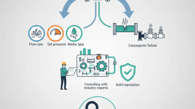
Choosing an air pressure relief valve in 2026 starts with the system, not the product listing. A valve that looks suitable on a screen may still respond too slowly, release too little air, or use a connection that does not fit the line. Note the vessel’s maximum allowable pressure, normal operating range, required set pressure, and expected flow rate before comparing models. Small details matter: a compressor cycling near its limit, a narrow outlet pipe, or moisture collecting around a fitting can affect performance. Check the manufacturer’s pressure-flow curves, temperature range, materials, and installation guidance. Do not choose by port size alone.
This guide explains how to match system requirements to a reliable air pressure relief valve, assess construction and adjustment options, and review testing and documentation. It also covers maintenance access, discharge direction, and behavior during routine operation—not just during an emergency. Start with verified equipment data, then confirm compatibility with the supplier or a qualified technician when the application is unclear. That sounds tidy. Real systems are messier. A specification sheet cannot reveal every vibration, pressure fluctuation, or awkward installation angle. Treat selection as a documented engineering decision, and review it if operating conditions change. The right valve is not simply the one with the highest rating; it is the one that protects the system while allowing it to operate as intended.
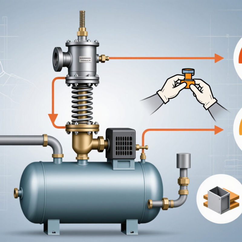
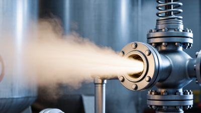
An air pressure relief valve is a last line of protection, not a pressure-control device for everyday operation. If pressure rises beyond its set point, the valve opens and releases air, helping prevent damage to a receiver, piping, or connected equipment. The opening should be clear and safely directed. A blocked outlet can undermine the protection. That matters.
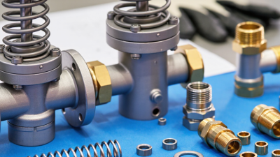
When choosing a valve, match its set pressure to the system’s permitted operating limits, and check that its flow capacity can handle the potential pressure source. Also verify connection size, temperature range, materials, and any backpressure from the discharge pipe. A fitting that threads into place is not necessarily a suitable valve. Small details count.
For example, a compressor receiver may need different relief capacity from a small pneumatic line, even if both use compressed air. Check the equipment documentation and the valve maker’s technical data, then have a qualified professional review uncertain sizing. I would not rely on a pressure gauge alone; it shows pressure, but does not prove the relief valve will open correctly. Testing and maintenance should follow the valve’s instructions and the system’s service conditions. Assumptions creep in here, especially when a replacement looks identical. Verify the actual ratings.
Identifying Operating Pressure, Airflow, and Temperature Requirements
Start with the system’s real pressure range, not just the compressor’s nameplate. Record normal pressure, startup spikes, and the maximum pressure the protected vessel or line can safely withstand. The valve’s set pressure must protect that equipment while avoiding routine discharge during ordinary fluctuations. A gauge beside the receiver can reveal spikes that a control-panel reading misses.
Next, match relief capacity to the maximum air that could enter the protected section, including compressor output and possible regulator failure. The U.S. Department of Energy’s 2016 Improving Compressed Air System Performance sourcebook notes that leaks can waste 20–30% of compressed-air production in poorly maintained systems. That matters: a valve sized from average demand may not handle a fault. Check rated capacity at the intended set pressure, plus inlet losses and discharge backpressure. Small details count.
Temperature changes the choice, too. Compare the valve’s rated operating range with the hottest and coldest air it will actually see, including hot restarts and nearby equipment heat. Confirm that seals and internal materials suit those conditions. DOE’s sourcebook estimates compressed air uses about 10% of U.S. industrial electricity, and up to 30% in some facilities. A relief valve is not an efficiency fix, but a poor fit can waste air. Field conditions are messy; revisit your assumptions after installation and test under controlled procedures.
An air pressure relief valve should be selected around the system’s worst credible operating condition, not its average demand. Estimate the maximum air flow the valve may need to release, then compare it with certified capacity data at the actual inlet pressure. Compressor output, receiver volume, and downstream restrictions all matter. A valve that looks adequately sized on a catalog table may pass too little air once backpressure or temperature changes. Check the assumptions carefully.
Set pressure must protect the weakest pressure-rated component while avoiding nuisance opening during normal pressure fluctuations. Confirm the equipment’s allowable pressure and the system’s operating range before choosing a setting. Leave a practical margin between normal pressure and the set point. Too little margin can cause repeated discharge. Too much can leave equipment exposed. This balance is easy to underestimate, especially when gauges fluctuate or compressors cycle frequently.
Material choice depends on air quality and the installation environment. Dry, clean indoor air may suit common metal bodies and compatible seals, while moisture, oil, washdown, or outdoor exposure can change the requirement. Check seal compatibility, temperature limits, and corrosion resistance against real service conditions—not just the room’s average temperature. Keep the discharge path unobstructed, and account for noise and safe vent direction. I would also revisit the sizing if the compressor, receiver, or piping changes; an old selection can become a poor fit.
Use this guide to shortlist a valve, not as a substitute for a code-compliant pressure-relief calculation. Pressure ranges below are common examples, not design limits. Confirm the governing code, vessel rating, installation conditions, and certified valve data for the specific application.
| Application example | Typical operating pressure | Set-pressure selection basis | Capacity selection basis | Material considerations | Installation and verification checks |
|---|---|---|---|---|---|
| Workshop air receiver and general-purpose compressor | Often around 7–10 bar(g), depending on the equipment and process. | Set pressure must not exceed the receiver’s permitted maximum pressure and must comply with the applicable vessel and relief-device rules. Allow for normal operating pressure without setting the valve so high that the vessel is unprotected. | Use the maximum credible air inflow, commonly based on the compressor’s maximum delivery, and select a valve with certified capacity adequate for the required relieving conditions. Apply the code-required corrections. | A corrosion-resistant metal body and spring suitable for the site environment are common choices. Consider moisture, compressor oil carryover, and temperature. | Install directly on the protected vessel or on an approved connection. Keep the inlet unobstructed; do not place an isolating valve between the vessel and relief device unless specifically permitted by the governing rules. |
| Low-pressure pneumatic equipment or air receiver | Often around 5–7 bar(g); confirm the equipment’s actual working and maximum allowable pressures. | Base the setting on the lowest pressure rating among the protected components, subject to applicable code requirements. Do not use the normal regulator setting as a substitute for the equipment pressure rating. | Account for the maximum supply flow that could enter the protected volume, including regulator failure or another credible overpressure source where applicable. | Brass or stainless-steel components may suit clean, compatible, lower-pressure service; verify pressure rating, temperature limits, and compatibility with condensate or additives. | Check that the discharge cannot expose people to noise, hot air, oil mist, or projectiles. Protect the valve from contamination without restricting its inlet or outlet. |
| Higher-pressure compressed-air system | May be around 20–30 bar(g) in some systems; actual design pressure varies substantially by equipment. | Set pressure must be within the protected equipment’s allowable limits and consistent with the pressure-vessel code and system design. Verify pressure units and whether values are gauge or absolute. | Use the valve’s certified capacity at the applicable inlet pressure, backpressure, and relieving conditions. Do not select by pipe size alone; have the required capacity checked against the maximum credible inflow. | Choose body, spring, seat, and seals rated for the maximum pressure and temperature. Stainless steel may be appropriate for corrosive or demanding environments, subject to material compatibility. | Confirm pressure rating of every connection and discharge component. Check allowable backpressure and any capacity reduction stated in the valve documentation. |
| Oil-free instrument-air system | Often around 6–8 bar(g), but the required pressure depends on the instruments and distribution design. | Use the rating of the receiver or other protected component as the governing limit; coordinate the set pressure with normal operating pressure and the applicable code. | Size for the maximum credible compressor or supply flow into the protected section. Consider whether check valves, regulators, or multiple sources can affect the overpressure scenario. | For clean-air service, select materials and seals that do not introduce unacceptable contamination and that tolerate expected humidity and condensate. | Confirm the discharge route will not compromise a clean area. Follow the valve’s orientation and maintenance instructions, and preserve access for inspection and testing. |
| Example capacity check: compressor with 1.2 m³/min free-air delivery | Illustrative only: the compressor may operate at a system pressure such as 8 bar(g); this does not determine the relief-valve setting. | Determine the setting from the protected vessel’s rating and applicable rules—not from the compressor’s free-air-delivery figure. | Start with the compressor’s maximum credible delivery of 1.2 m³/min, then compare it with the valve’s certified capacity on a consistent basis. Convert or correct for the stated reference conditions, relieving pressure, temperature, and backpressure as required. | Choose materials for the actual air temperature, moisture, oil carryover, corrosion exposure, and pressure rating. | This is not a valve-size recommendation. A qualified designer must verify the capacity calculation, code requirements, and installation arrangement before selection. |
| Selection check | What to verify before ordering |
|---|---|
| Set pressure | Confirm the protected equipment’s maximum allowable working pressure (MAWP), the applicable code limits, normal operating pressure, and whether the stated pressure is bar(g), kPa(g), or another unit. |
| Relief capacity | Use certified capacity data for the actual gas and relieving conditions. Account for maximum credible inflow, temperature, inlet losses, and backpressure where required. |
| Valve type and certification | Select a device intended and certified for compressed-air or gas service and for the required pressure range. Check the applicable local regulations and inspection requirements. |
| Materials and environment | Verify body, trim, spring, and seal compatibility with moisture, oil, cleaning agents, ambient conditions, and operating temperature. |
| Connections and discharge | Check connection type and pressure rating, adequate inlet and outlet flow paths, allowable backpressure, safe discharge location, and maintenance access. |
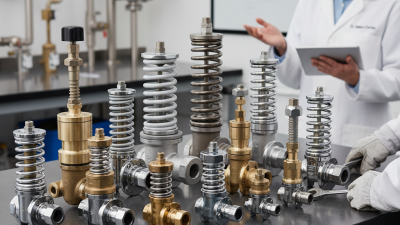
Choosing an air pressure relief valve starts with the system, not the catalog. Spring-loaded valves are common for compressed-air receivers and offer a straightforward design. Pilot-operated models can suit larger systems or tighter operating ranges, but they need clean control air and careful maintenance. Low-pressure breather valves serve storage tanks; they are not interchangeable with certified safety valves. Small distinction. Big consequence.
Compare applicable standards before comparing prices. Depending on the equipment and location, requirements may reference ASME Section VIII, ISO 4126, or relevant pressure-system codes. Confirm the current edition and local adoption with a qualified engineer or inspector. Standards address design and testing, while the installation still affects performance. A blocked outlet, excessive backpressure, or undersized discharge pipe can undermine an otherwise suitable valve.
For 2026 specifications, check the set pressure, certified air capacity, inlet size, temperature range, materials, and allowable backpressure. Match capacity to the compressor’s maximum flow and the receiver’s pressure rating; do not select by connection size alone. Ask for test documentation and clearly stated tolerances. Then review how the valve will be mounted and inspected. Real installations are messier than datasheets suggest, and I would recheck assumptions whenever operating conditions change.
Valve types, standards, and a code-based pressure-setting reference
The chart shows commonly stated ASME Section VIII pressure-setting tolerances: ±2 psi for settings up to and including 70 psi, and ±3% above 70 psi. These are tolerance limits, not recommended operating pressures or valve capacity ratings. Confirm the applicable code edition, jurisdiction, and certified product datasheet before selection.
| Type | Typical consideration | Check before choosing |
|---|---|---|
| Conventional spring-loaded | Direct-acting design; commonly used where outlet backpressure is limited. | Set pressure, capacity, and built-up or superimposed backpressure. |
| Balanced-bellows spring-loaded | Designed to reduce the effect of backpressure on valve operation. | Bellows limits, outlet conditions, and material compatibility. |
| Pilot-operated | Pilot control can suit applications requiring tight operating margins or higher capacity, depending on design. | Pilot arrangement, minimum operating pressure, contamination risk, and backpressure limits. |
Use the applicable pressure-vessel and relief-device requirements for the installation. ASME Section VIII addresses pressure vessels and their protection; API 520 covers sizing, selection, and installation guidance for pressure-relieving devices; ISO 4126 sets requirements for safety devices against excessive pressure. Verify the exact scope and adopted edition for the project.
Checking Installation, Testing, and Maintenance Requirements
A suitable valve must match the system’s operating pressure, airflow capacity, air temperature, and connection size. Check its documentation before purchase, including required installation orientation and discharge arrangements. A valve that fits the pipe may still be wrong for the system. Small details matter.
During installation, depressurize the equipment and follow the manufacturer’s instructions. Keep the inlet path clear and within specified pressure-drop limits. Support discharge piping independently so its weight does not strain the valve. Route the outlet away from people and places where released air could cause harm. One detail I would double-check is whether nearby fittings or a closed isolation valve could obstruct relief. It is easy to miss during a busy installation.
Testing should confirm the opening pressure, reseating behavior, and leakage using calibrated equipment or an approved in-place method. Use a test lever only when the valve instructions permit it and conditions are safe. Set maintenance intervals according to the instructions, service conditions, and inspection history. Look for corrosion, deposits, damaged seals, loose connections, and blocked outlets. Keep records of test results and repairs; they help reveal drift over time. After servicing, verify performance again. A visual check alone cannot confirm the set pressure.