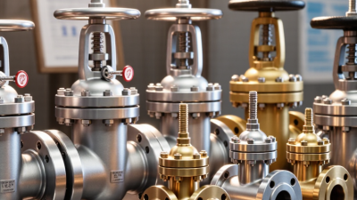
A high pressure relief valve is more than a line item on a piping diagram. It is the engineered safeguard between normal operation and damaging overpressure. In 2026, the right choice depends on pressure range, fluid properties, backpressure, required capacity, and maintenance access. A spring-loaded valve may suit a straightforward service. A pilot-operated design can offer tighter operation at higher pressures. Balanced-bellows and thermal relief valves address different backpressure and trapped-liquid conditions. Small details matter. A fouled inlet, undersized discharge line, or poorly chosen set pressure can undermine an otherwise sound selection.
Industry sources help frame the decision. API 520 and API 521 provide guidance on sizing, selection, installation, and disposal systems; ISO 4126 sets requirements for safety devices against excessive pressure. Grand View Research’s Pressure Relief Valve Market Size, Share & Trends Analysis examines the market by valve type and end use, while U.S. Chemical Safety Board investigation reports document real process-safety failures and their consequences. These sources do not replace a site-specific engineering review. They do show why selection must consider both performance and operating context. Process-safety pioneer Trevor Kletz is often quoted: “If you think safety is expensive, try an accident.” It is a blunt reminder.
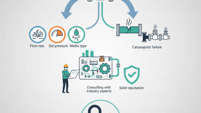
This guide compares the leading high pressure relief valve types expected to matter in 2026, including their operating principles, strengths, and trade-offs. It also highlights practical checks: certified capacity, materials compatibility, set pressure, discharge conditions, and inspection needs. No single type fits every service. The safest shortlist starts with the system’s documented design basis—not a catalog headline.
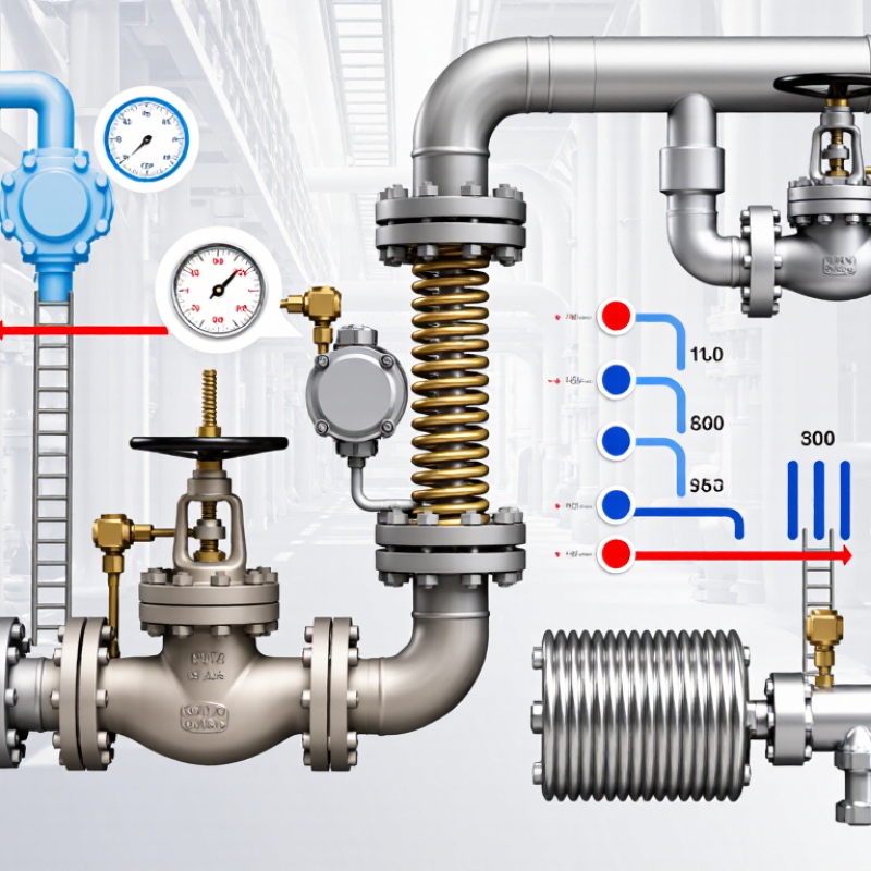
High-pressure relief valves protect vessels and piping by opening when pressure reaches a defined limit. Their performance depends on three linked values: set pressure, lift, and capacity. Set pressure is the inlet pressure at which a valve begins to open under specified test conditions. It should be checked against equipment limits, normal operating pressure, and expected pressure variations—not chosen by guesswork.
Lift describes how far the disc moves from its seat. Greater lift can expose more flow area, but actual behavior depends on valve design and service conditions. Spring-loaded valves and pilot-operated valves may respond differently as pressure rises. Small detail, big consequence. Use certified flow data, not appearance, to assess performance.
Capacity is the amount a valve can discharge under stated conditions, often measured as mass or volume per unit of time. It must cover the credible relieving load, considering the fluid, temperature, and backpressure. Reaching set pressure is not enough. Not just the valve. Piping layout, fouling, and changing process conditions can affect the result. Record sizing assumptions and review them when operating conditions change.
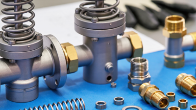
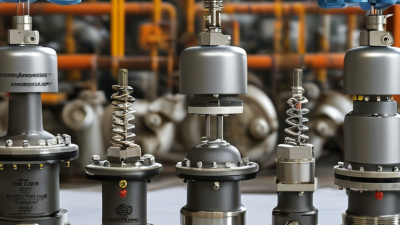
Spring-loaded pressure relief valves respond directly to inlet pressure, but their internal design changes how they handle backpressure. Conventional valves are usually simplest when discharge backpressure stays low and predictable. If backpressure varies, it can shift opening pressure or reduce capacity. Balanced-bellows designs reduce that effect by isolating the spring from much of the outlet pressure. A bellows is not magic: corrosion, fatigue, or a leak can compromise its balancing function. Piston designs use a piston as the moving element; their suitability depends on seal materials, fluid compatibility, and the manufacturer’s tested operating limits. Small details matter.
API 520 Part I bases sizing on certified discharge coefficients and correction factors, so nominal pressure alone cannot establish capacity. API 526’s published standard-orifice table spans 0.110 to 26.0 square inches. That range helps engineers match capacity to a calculated relieving load, rather than selecting by connection size. API 521 also guides evaluation of relieving and depressuring scenarios. These standards are useful references, but actual selection still requires process data, including fluid state, temperature, and built-up backpressure. I would not treat a bellows option as an automatic upgrade; its service conditions need careful review.
Tips: Record normal and worst-case outlet pressure, then compare it with the valve’s permitted backpressure. Check bellows material and piston seals against the process fluid. Have a qualified engineer verify sizing and set pressure against applicable codes and documented operating conditions.
Pilot-operated relief valves use process pressure to control a main valve through a smaller pilot. At normal pressure, the pilot keeps the main valve closed. When pressure reaches the set point, the pilot changes state and allows the main valve to open. The result can be tighter operation near set pressure than with some spring-loaded designs. That matters.
These valves are often considered for high-pressure vessels, compressors, and systems with changing operating pressures. They can also help where backpressure affects conventional valve performance, depending on the design. But they are not ideal for every service. Dirty fluids may obstruct small pilot passages, and temperature or vibration can affect performance. A clean-looking installation is not proof that the sensing line is clear.
API 520 sizing starts with the required relief rate and the fluid’s properties at relieving conditions. Engineers also account for set pressure, allowable overpressure, backpressure, and applicable capacity factors. The calculated area helps determine the required valve size, but it does not replace checking certified capacity and installation limits. Inlet pressure loss deserves attention; it is easy to overlook on a drawing. Small details count. Actual conditions can differ from neat calculation inputs, so assumptions should be reviewed against operating data and the specific valve design.
High-Pressure Service · 2026 For high-pressure service in 2026, the key choice is not simply spring-loaded versus pilot-operated relief valves. The ASME Section VIII, Division 1 benchmarks define permitted vessel accumulation: generally 10% for one device, 16% when multiple devices protect the vessel, and 21% for qualifying fire exposure. These limits are measured above maximum allowable working pressure, not added to the valve’s set pressure. See ASME BPVC Section VIII, Division 1, UG-125(c); confirm the applicable edition and vessel conditions before sizing.
That distinction matters. A spring-loaded valve is often selected for straightforward, robust protection, while a pilot-operated valve can suit applications needing tighter operating margins or high set pressures. But neither type automatically makes a 16% or 21% case acceptable. The relieving scenario, certified capacity, inlet pressure loss, and discharge-system backpressure all matter. A small line restriction can undermine an otherwise correct calculation.
Check the details For example, a vessel with a 1,000-psi MAWP has benchmark pressure levels of 1,100, 1,160, and 1,210 psi, respectively. Those figures are not universal setpoints; code provisions and service conditions affect their use. I have seen teams focus on the headline percentages and overlook operating variability. That is an easy mistake. Verify the governing code, documented scenario, and valve certification with a qualified pressure-relief engineer.
Pressure class is a starting point, not a complete selection rule. Match the valve’s rated pressure and temperature to the vessel’s maximum allowable working pressure and operating conditions. ASME Boiler and Pressure Vessel Code, Section VIII, generally permits 10% pressure accumulation above MAWP for a single relief device in non-fire service. Fire exposure and multiple-device arrangements follow different limits. Check the applicable code edition and scenario.
Materials must suit the fluid, temperature, and corrosion risks. A stainless-steel body may resist some corrosive services, but trim, seals, and deposits matter too. Ask whether the fluid carries grit, polymerizes, or can freeze. Small details can change maintenance needs. I would not choose by body material alone.
Backpressure can alter capacity and opening behavior. API 520 Part I sizing procedures account for backpressure, while API 521 addresses relief-system design and disposal. Conventional spring-loaded valves may suit low-backpressure systems; balanced-bellows or pilot-operated designs can be preferable when outlet pressure varies. Verify allowable backpressure against certified valve data, especially with long discharge lines. The service decides. A clean steam line and a flashing liquid line are not interchangeable cases, even at similar set pressures. Allow room for uncertainty: actual operating data may be incomplete, and a conservative assumption should be documented, not hidden.