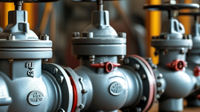
A thermal relief valve protects a small, trapped volume of liquid when temperature changes raise its pressure. Picture liquid held between two closed valves in a sun-warmed pipe: the fluid expands, but has nowhere to go. Pressure can climb quickly. That is the problem this compact device is designed to address.
Engineering author Henry Petroski’s phrase, “To engineer is human,” offers a useful reminder: dependable protection depends on understanding how a system is actually used. A thermal relief valve normally stays closed. When pressure reaches its set point, the valve opens and releases a limited amount of fluid to a designated lower-pressure location. As pressure falls, it closes again. Simple in principle. Easy to misapply.
This guide explains what a thermal relief valve does, how its internal mechanism responds to pressure, and where engineers commonly install one. It also considers selection factors such as fluid compatibility, pressure rating, temperature range, and discharge routing. These details matter; a valve sized or installed without regard to the system can fail to protect the trapped section. A thermal relief valve is not a substitute for a system’s primary pressure-relief protection. That distinction deserves attention, especially when drawings do not show every possible isolation point. Actual sizing and installation should follow the valve manufacturer’s instructions and be reviewed by a qualified engineer.
A thermal relief valve is a pressure-protection device for liquid trapped in a closed section of piping or equipment. When nearby heat warms the liquid, it expands. Because the liquid has little room to move, pressure can rise even when the temperature change seems small. A valve may protect a blocked pipe between two closed valves, a pump casing, or a section exposed to sunlight. It responds to pressure, not simply to temperature. That distinction matters.
When pressure reaches the valve’s set point, a spring-loaded mechanism opens and releases a small amount of liquid. The discharge may return to a lower-pressure part of the system or flow to an approved collection point, depending on the design. Once pressure falls, the valve closes again. Often, the movement is too small to notice. A thermal relief valve is not meant to regulate routine operating pressure or replace a correctly designed pressure-protection system. The set point, materials, and discharge route must suit the fluid and operating conditions. I would not assume one valve fits every trapped section; checking the actual layout is easy to overlook. A qualified engineer should verify its selection and installation.
A thermal relief valve protects liquid trapped between closed valves or other boundaries. When temperature rises, the liquid expands and pressure can build quickly. The valve opens at a preset pressure, allowing a small amount of liquid to escape. It then closes as pressure falls. A small part. Big consequence.
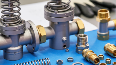
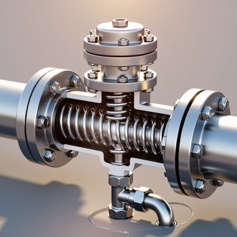
The valve body contains the flow path and connects to the protected line. Inside, a spring presses a poppet or disc against a seat. The seat forms the seal when the valve is closed. Rising pressure pushes the poppet away from the seat, overcoming the spring force. Some designs include an adjustment mechanism, while others have a fixed setting. The outlet must lead to a safe, suitable location; its routing matters.
Material choice and pressure rating should match the fluid, temperature, and system conditions. In practice, dirt or wear can prevent a clean seal, so a valve may drip or fail to open as intended. Not every design is adjustable or serviceable. Check the valve’s specifications and installation guidance, and have qualified personnel assess uncertain applications. Real installations are rarely perfect, which is exactly why clear inspection access helps.
A thermal relief valve protects liquid trapped in a closed section of piping or equipment. As the liquid warms and expands, pressure can rise; when it reaches the valve’s set pressure, the spring-loaded poppet opens and releases a small amount of liquid.
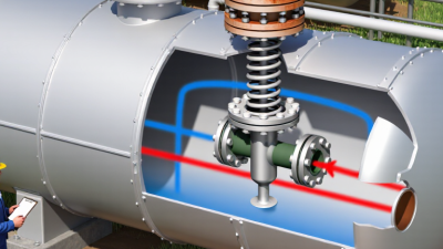
Key components: The inlet senses system pressure; the poppet seals the flow path; the spring holds the poppet closed until pressure reaches the set point; and the outlet directs relieved liquid to a safe return or collection point.
The chart shows approximate free-volume expansion of water relative to 20°C, calculated from water-density data. In a confined system, actual pressure rise depends on the liquid, temperature change, pipe and vessel flexibility, and system layout.
A closed system can trap liquid between two shut valves, inside a pipe, or within a pump casing. When the liquid warms, it expands, but the confined space barely changes. Even a modest temperature rise can therefore create a sharp pressure increase. Heat has nowhere to go. A sunlit pipe run or a nearby motor can supply enough warmth to matter, even when the system seems idle.
A thermal relief valve responds to that pressure rise. Once pressure reaches its set point, the valve opens and releases a small amount of liquid to a suitable return or collection point. This gives the remaining liquid room to expand. As pressure drops, the valve typically closes again. A small volume matters. The discharge path must be planned carefully; sending hot or hazardous fluid toward people or equipment creates a separate risk.
These valves address pressure caused by thermal expansion in trapped liquid, not every form of overpressure. They should not be treated as a substitute for a properly selected system pressure-relief device. Correct placement, pressure rating, fluid compatibility, and discharge routing all matter. Check the system documentation and have a qualified professional assess the installation. One detail is easy to miss: a valve cannot relieve pressure if its inlet is isolated from the trapped section.
A thermal relief valve protects a liquid-filled section of pipe or equipment when heat causes pressure to rise. In common spring-loaded designs, rising inlet pressure pushes a poppet against its spring. Once pressure reaches the valve’s set point, the poppet lifts and lets a small amount of fluid escape to a suitable return or collection point. The opening may be brief. It still matters.
As fluid leaves, pressure falls. When it drops below the valve’s reseating pressure, the spring pushes the poppet closed again. IAPWS-95 water-property data show density falling from about 998.2 kg/m³ at 20°C to 995.7 kg/m³ at 30°C, equivalent to roughly 0.25% volume expansion. In a blocked, rigid line, even that small growth can create a sharp pressure increase. The detail that is easy to overlook: reset depends on correct valve selection and a clear discharge path, not just the spring.
Tips: Verify the set pressure against the equipment’s allowable limits, and route discharge where released fluid can be managed safely. Keep the outlet unobstructed. Check for leaks or sticking during maintenance; a valve may not reseat cleanly every time.
A thermal relief valve protects liquid trapped between closed valves or other barriers. As the liquid warms, it expands and pressure can rise sharply, even in a small pipe section. The valve opens at its set pressure and releases a limited amount of fluid. Small volumes matter. Common applications include hydraulic equipment, isolated water lines, heat exchangers, and liquid-filled piping exposed to sunlight or nearby machinery.
Install the valve as close as practical to the trapped section, with no shutoff valve separating it from the volume it protects. Set pressure must exceed normal operating pressure but remain below the pressure rating of the weakest component. Check the valve’s capacity against the expected thermal expansion; it is not a substitute for a main system pressure-relief valve. Route discharge to a suitable, visible location or return line, following the fluid’s temperature and compatibility requirements. A clean route is essential.
Before installation, confirm flow direction, connection size, materials, and the manufacturer’s pressure and temperature limits. Support the piping so vibration or pipe weight does not strain the valve. In service, inspect for leaks, corrosion, and blocked discharge paths, then test according to the equipment maintenance plan. One detail is easy to overlook: a valve that opens correctly can still create a hazard if its discharge sprays onto a hot surface or walkway.